
Low Level Vacuum Preloading
Release time:Jul 24,2023
Number of views:
Share:


Low level vacuum preloading method and its reinforcement mechanism
The traditional vacuum preloading method is to perform vacuum load preloading on the construction site before building construction, so that the foundation can basically complete consolidation settlement and improve the strength of the foundation soil under vacuum load pressure. This method requires setting up sand wells or plastic drainage boards in the reinforced soft clay foundation, and then laying a sand cushion layer on the ground, which is covered with an airtight sealed plastic film to isolate it from the atmosphere. Through a suction pipeline buried in the sand cushion layer, a vacuum device is used to exhaust the air inside the film, creating a pressure difference inside and outside the film, which becomes a load acting on the foundation, The foundation solidifies with the increase of isotropic pressure.
The low level vacuum preloading method is a new method of vacuum preloading to reinforce soft soil foundation, which uses hydraulic fill mud instead of plastic film as the sealing layer of the vacuum system. This method is different from the traditional vacuum preloading method in that the horizontal vacuum pipeline network is arranged at the bottom of the hydraulic fill mud, and the vacuum system will act on both the hydraulic fill mud layer above it and the soft soil foundation below it. Therefore, for the hydraulic fill soil located above it after reinforcement, the horizontal vacuum pipeline network is located at the bottom, so this vacuum preloading method is called the low level vacuum preloading method.
Construction process procedures
Taking the embankment as an example, a landslide occurred during the implementation of river dredging and the reinforcement of the embankment body using dredged soil. After comprehensive comparison and selection, it was decided to use the low level vacuum preloading method for treatment. After several years of trial operation, the reinforcement effect is good.
(1) Site leveling. Use a bulldozer to flatten the soil in the area to be reinforced and remove any debris.
(2) Temporary cofferdam filling. After the completion of site leveling, excavate an isolation ditch and fill two cofferdams on both sides of the area to be reinforced. The cofferdams should be compacted layer by layer, stable, airtight, and impermeable to ensure the formation of a closed circle around the reinforced area.
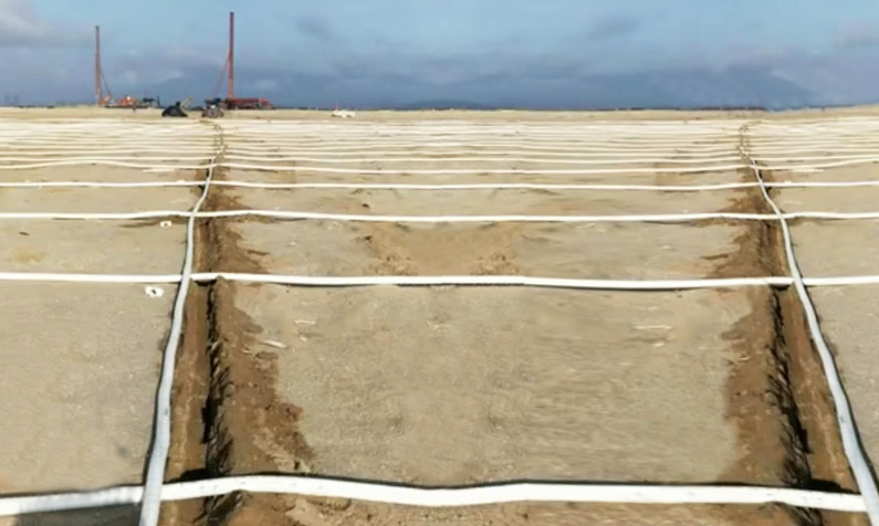
(3) Drainage reinforcement system. Including vertical drainage body and horizontal drainage body. The vertical drainage body mainly consists of plastic drainage boards, while the horizontal drainage body consists of a horizontal pipe network, a vacuum collection well, and a vacuum drainage unit. The upper reinforcement system strengthens the dredged soil filled in the cofferdam, and also consists of vertical and horizontal drainage systems.
Vertical drainage body. The plastic drainage board for the foundation reinforcement system adopts SPB-B type, with a specification of 100 × 4mm. The spacing between boards is 0.9m, the row spacing is 0.78m, and the insertion length is 15m. The width direction of the board is parallel to the length direction of the reinforcement area, and a crawler type insertion machine is used to complete the insertion operation. The insertion sequence is: positioning; Install plastic drainage boards; Insert the plastic drainage board and pull out the guide pipe; Cut off the drainage board; Shift to start the next task. The average insertion depth of plastic drainage boards is 15.5m, and after insertion, the exposed ground should not be less than 0.5m. b. Horizontal drainage body. The horizontal pipeline network system includes the construction of branch pipes and the installation of main pipes. Branch selection Φ 60PVC double corrugated pipe, longitudinally extending along the plastic drainage pipe and overlapping with the plastic drainage plate, is laid on both sides of the main pipe, with a slope of 1/1000. The spacing is 0.78m, with one end of the branch pipe vertically embedded with the main pipe and the other end closed. Main pipe selection Φ 200PVC double wall corrugated pipe, with one end closed and the other end embedded into a vacuum water collection well through a rubber hose. The main pipes are connected through a socket, with built-in rubber rings. Each pipe is 25m long and has a slope of 1/600c. The vacuum water collection well is built in the middle of the reinforcement area, in a circular platform shape. The bottom of the well is a reinforced concrete cast-in-place bottom plate, and the wall of the well is a brick structure for waterproofing treatment. The inner diameter of the lower mouth is 1.6m, the inner diameter of the upper mouth is 0.5m, and the well height is 3m. The upper part of the wellhead is connected Φ 400 steel pipes, whose length is required to be higher than the highest hydraulic fill level, and Submersible pump units are arranged in the well.
Observation system. After the construction of the plastic drainage board and branch pipe is completed, the observation system can be buried. The observation equipment of this project is buried (settlement marker, S pore Piezometer are averagely arranged in the reinforced stratum, that is, the depth is 15m, 12m, 9m, 6m, 3m respectively), and three vacuum pressure gauges are installed on the vacuum pump and the tail end of the horizontal branch pipe, one is installed on the vacuum pump, and the other two are installed on the tail end of a branch pipe on both sides of the main pipe. Its burial time cannot be later than the completion time of the vacuum pipeline network system. (5) Hydraulic fill engineering. After the completion of the above project, mud can be blown into the cofferdam for sealing. Before hydraulic filling, it is best to lay plastic film inside the cofferdam to the top of the cofferdam to prevent air leakage during the reinforcement process. During hydraulic filling, continuity should be maintained and the position of the hydraulic filling port and overflow port should be moved at any time according to changes in the mud surface to ensure the smoothness of the mud surface. (6) Vacuum preloading reinforcement. When the hydraulic reclamation of the mud seal layer is completed, the machine pump system can be started, and the vacuum pump can be used to create a continuous negative pressure in the hydraulic reclamation soil layer, so that the pore water in the soil layer can be separated under the negative pressure, and the Submersible pump can be used to discharge, so as to achieve the purpose of strengthening the soil layer. Vacuum operation requires water to be drained and pressure to be transmitted through suspended pipes. As the pressure gradually increases, the drainage amount decreases. During the drainage process, the operation of the unit should be appropriately arranged based on the amount of water discharged. After implementing vacuum preloading, the consolidation degree of the hydraulic fill layer shall not be less than 80%. (7) Post plastic surgery. After the vacuum operation is completed, the cofferdam earthwork is backfilled into the drainage ditch, and the sludge in the isolation ditch is excavated using an excavator. The cofferdam earthwork is then compacted and leveled, and the entire reinforcement and elevation process is completed.
Key points of construction quality control
(1) Material selection control. According to the quality inspection standard for plastic drainage boards (JTJ/T), the appearance quality and quality assurance data of the raw materials used, such as plastic drainage boards and corrugated pipes, are inspected, with a focus on whether the main performance indicators such as longitudinal water flow rate, composite tensile strength and elongation, filter membrane tensile strength and elongation, filter membrane permeability coefficient, and equivalent pore size of the filter membrane meet the design requirements. Strengthen sampling and testing, and control the storage period of plastic drainage boards from production to installation to ensure good results.
(2) Plug in control. When positioning the insertion machine, the deviation between the control pipe shoe and the insertion plate position mark is within ± 70mm. During the insertion process, pay attention to checking the verticality of the pipe sleeve at any time, and the deviation should not exceed ± 1.5%. The length of the control board return strap should not exceed 500mm, and the number of return straps should not exceed 5% of the total number of installed ones. During the insertion process, visually inspect the plastic drainage board at any time to prevent twisting, tearing, and damage to the filter membrane.
(3) Record data control. Establish a work log that reflects the quality status of the project, truthfully recording the dynamic quality situation during the construction process, as well as the material, mechanical environment, and methods that affect the project quality. Especially, keep timely records of the construction of plastic drainage boards, including the depth of installation, length of return straps, number of return straps, number and position of replacement straps, plate position, verticality, exposed length, and the situation of extension plates.
(4) Vacuum pressure control. When starting vacuum preloading, it is important to ensure the strength and continuity of the pressure. The vacuum negative pressure loading requirement should be above 80kPa. When the surrounding power cannot meet the construction requirements, it is best to have a self-contained power supply. At the same time, control the pumping speed to avoid uneven settlement.
(5) Control of external conditions such as mud seal layer. Due to the fact that the hydraulic fill mud layer not only serves as a seal for the soft soil base, but also consolidates, it is particularly important to choose an appropriate thickness of the hydraulic fill mud layer to ensure its sealing performance, so that its consolidation lags slightly behind the consolidation of the soft soil foundation. Generally speaking, the thickness of the hydraulic fill mud layer should be 0.8~1.2m. As a sealing layer, the hydraulic fill soil should not contain a large amount of impurities such as stone chips, and the foundation should not have a thick breathable sand layer, otherwise it will also affect the vacuum preloading effect.
